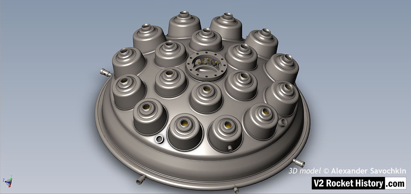
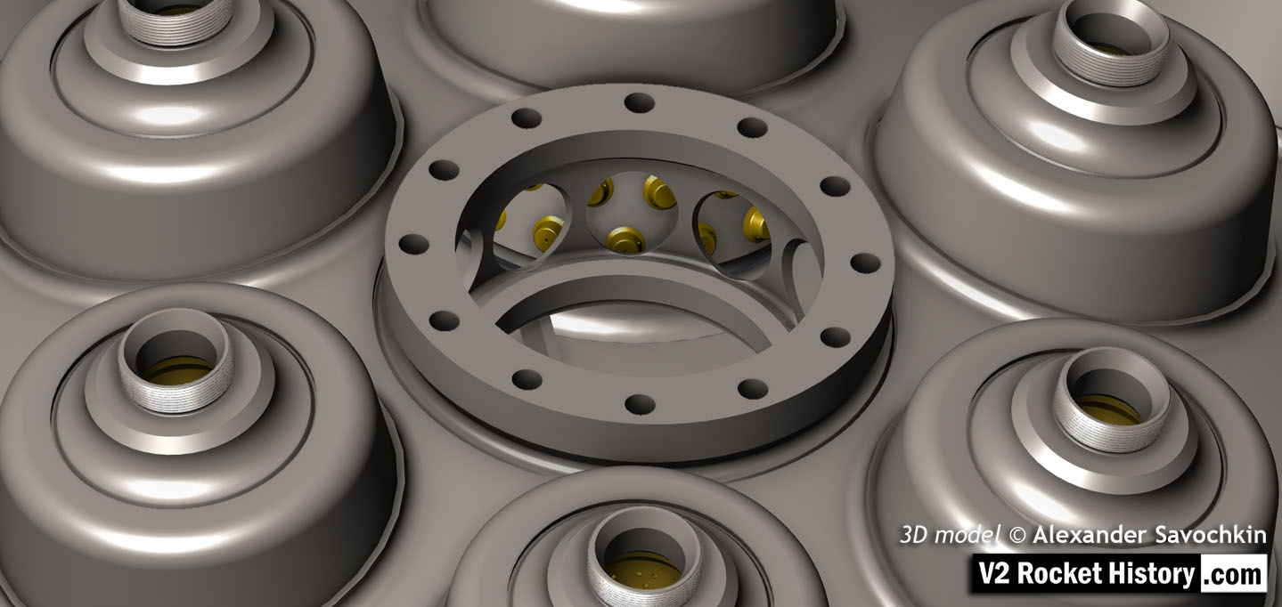
18-pot Upper Veil Manifold detail
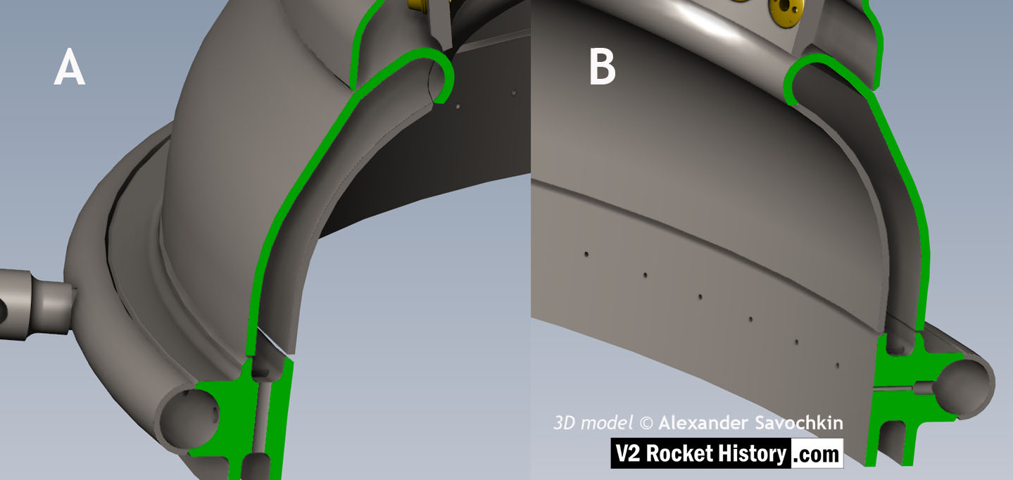
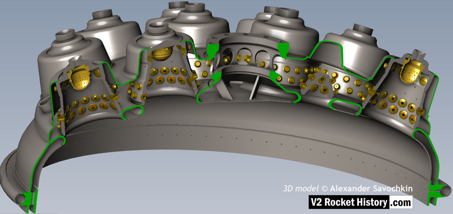
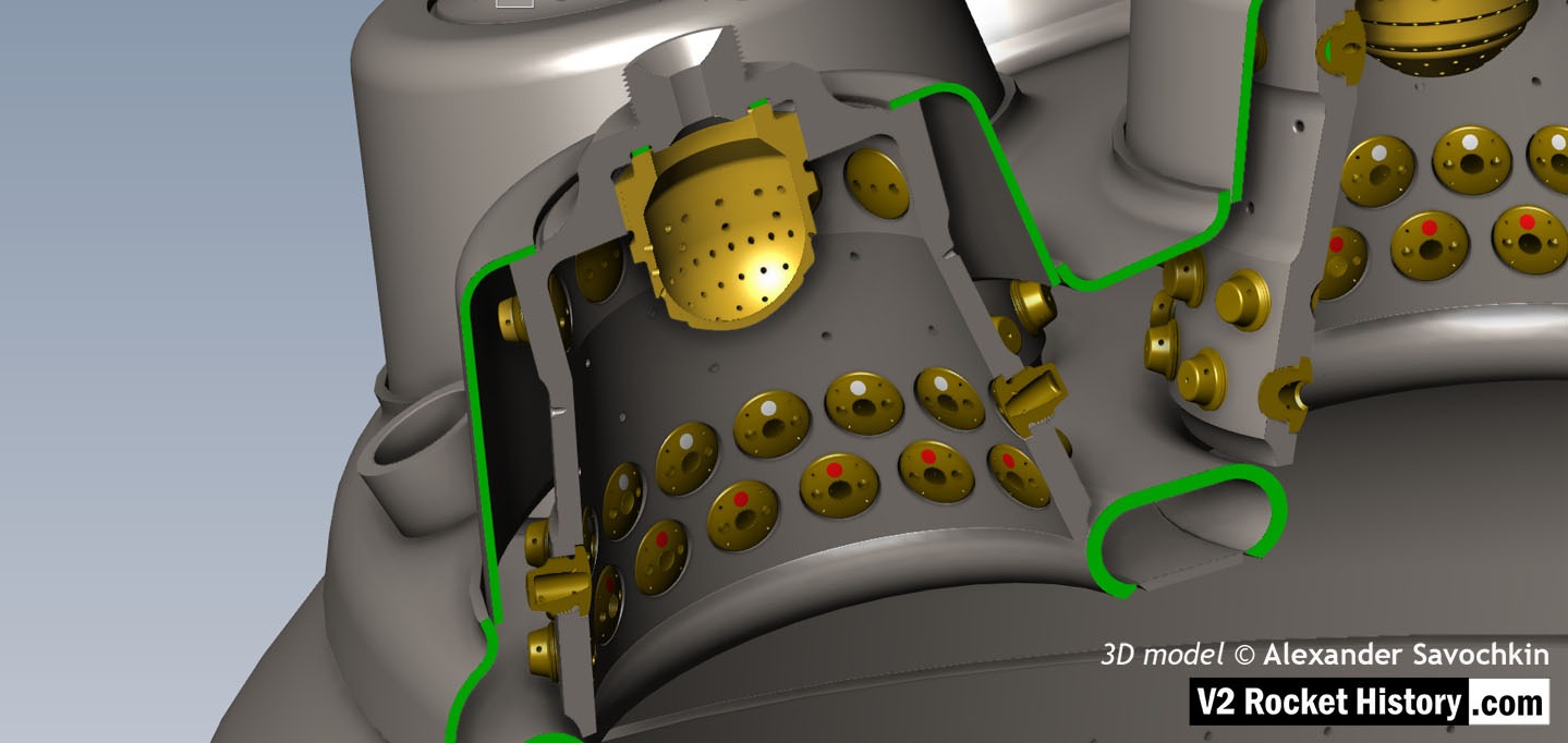
Close-up detail showing independent pathway for fuel passing into injector head and fuel passed down from the head to be used for veil cooling system. Fig. A shows vertical passages for overall fuel feed to the head and Fig.B shows horizontal pathway for veil coolant fed from the head via the veil coolant distributor ring or manifold. 3D model by Alexander Savochkin
Album: Anatomy of the V2: 18-pot injector head
Categories: Anatomy of the V2 Combustion
Tags: